A serial console enables you to configure the RaspberryPi without having to connect it to a display or network, or you might have old hardware like a router or similar lying around at home and want to know what's going on inside. With a bit of luck, there's a hidden serial interface that's not actually intended for use by a "normal user".
First of all, opening and modifying devices will almost certainly void your warranty if there is one on the device. The other thing is that you only do this with devices that belong to you. If you unscrew things that don't belong to you and are asked to pay for it, don't claim you didn't say anything.
So what do we need to get started?
First of all, a USB <-> TTL adapter
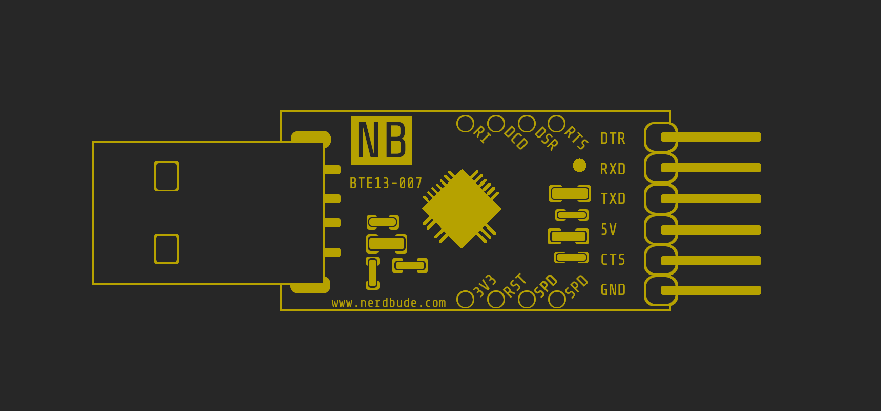
The adapter (see picture) is available online for between €3.00 and €30.00. In this case, it has a USB 2.0 Type A plug that goes into the computer and 6 pins that are wired to our serial interface. Jumper cables are recommended for wiring; they can simply be plugged into the pins of the adapter and any pins that may be present on the interface. If there are no pins on the interface but only soldering points, you can simply shorten the jumper cables and solder them on. Jumper cables are available in different colors and you should use them to keep track of everything.

What you also need is a device with a serial interface. Most routers have one, but so do other devices that run an OS (usually Linux). How do you identify the interface? Things that are suspect here include soldering points that are not being used. In some cases, however, the interfaces also have pins like our adapter. This makes it much easier, of course, because you only have to plug in the jumper cables instead of soldering them in.

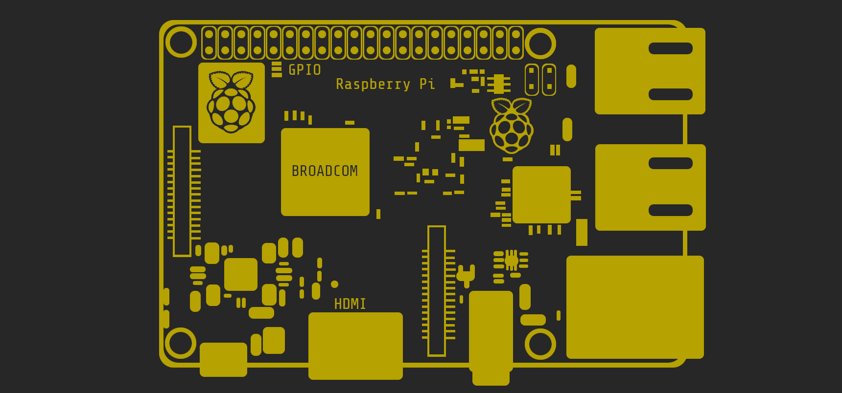
Since I don't have a device that I want to take apart or a device with an interface at the moment, we can try it out on a Raspberry Pi. Most people should have one lying around at home to experiment with. We're using the standard OS Raspian here. However, it should work with any other supported OS. As usual with the Raspberry Pi, we write the OS to the SD card and insert it.
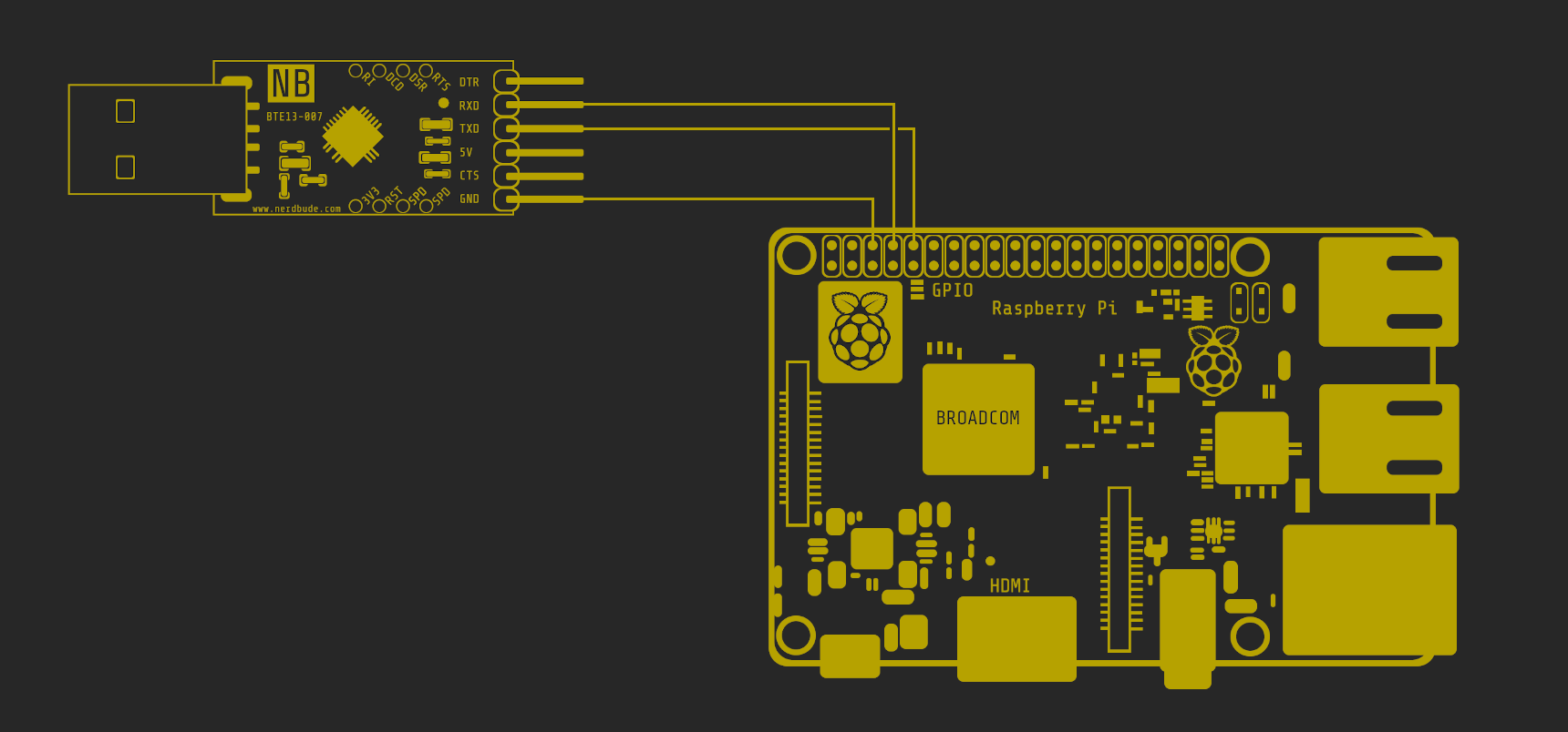
Now we need to connect the pins of our adapter to the GPIO pins of the Raspberry. To do this we need the following 3 pins on the adapter and the Pi:
- GND (Ground)
- RXD (receive data)
- TXD (transmit data)
You can find the GPIO pin assignment of the Raspberry Pi online. Pay attention to the model, as the pin assignment differs between different models.
Now the adapter just needs to be connected to the computer. It doesn't really matter which computer it is. Any OS can basically talk to the Raspberry Pi via the serial interface. For Windows you need the PuTTy tool and for Linux and macOS we use the terminal tool "screen" (preinstalled on Linux and macOS).
It is used as follows:
Linux / macOS
shell
screen -h
But before we can work with "screen", we need the hardware address of the adapter.
macOS / Linux:
shell
ls -l /dev/tty.*
shell
crw-rw-rw- 1 root wheel 33, 2 3 Feb 06:59 /dev/tty.Bluetooth-Modem
crw-rw-rw- 1 root wheel 33, 0 3 Feb 06:59 /dev/tty.Bluetooth-PDA-Sync
crw-rw-rw- 1 root wheel 33, 8 3 Feb 11:28 /dev/tty.PL2303-00001004
crw-rw-rw- 1 root wheel 33, 0 3 Feb 06:59 /dev/tty.Bluetooth-PDA-Sync
crw-rw-rw- 1 root wheel 33, 8 3 Feb 11:28 /dev/tty.PL2303-00001004
Let's assume that a PL2303 chipset from Prolific is installed, so the latter is the address we are looking for. Now we can access the serial interface via the adapter using the screen, using the following command:
shell
screen /dev/tty.PL2303-00001004 115200
115200 sets the baud rate here - in other words the transmission speed.
Now connect power to the Raspberry Pi and you should be able to see the Raspberry Pi's boot sequence in the terminal or log in to it.
Of course, this is just the basis for many of the fun things that are possible with the serial interface. The only limit is your imagination and the availability of the interface.
Have fun trying it out.
[~] BACK