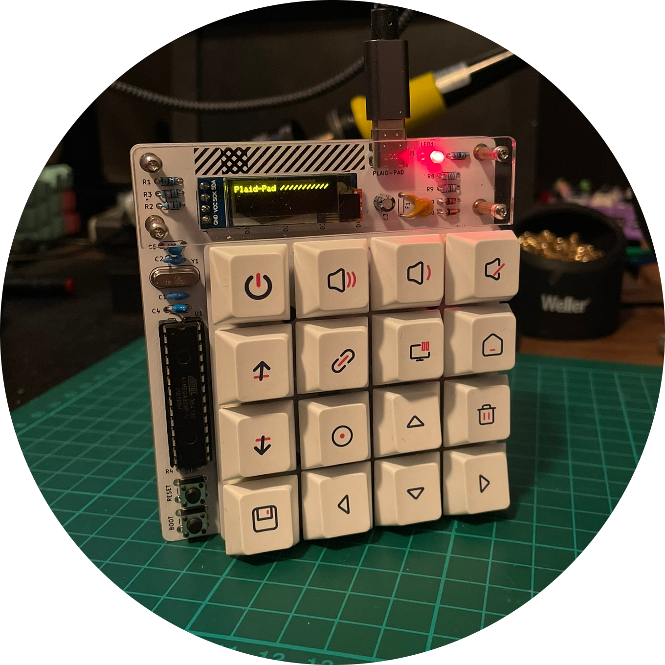
Before Christmas I stocked up again at Ben's KEYCAPSSS. I can say that he is my number 1 port of call for keyboard stuff. The Plaid Pad will be used here as a podcast macro pad. The most important Audacity shortcuts will be placed on the keys, but I'm still working on the final layout. The Plaid Pad comes as a complete kit, i.e. almost all the parts that are needed are included (excluding switches and keycaps).
The switches on the Plaid Pad are Durock Koalas:
- Creme Polycarbonat Top
- Creme Nylon PA Bottom
- POM Stem in Off-Black
- Gold-plated Spring
- 67g Bottom out
- Tactile
The keycaps are a no-name set from AliExpress. It looks nice and has enough caps with icons that fit perfectly on the pad.
So switches and caps are clear. What is included in the kit:
- 1x PCB
- 1x Backplate
- 1x 4x4Switch Plate
- 16x 1N4148 Dioden
- 2x Zener Dioden
- 1x Resetable Fuse
- 1x Electrolytic capacitor
- 2x 1.5k Ohm resistors
- 2x 75 Ohm resistors
- 1x 10k Ohm resistors
- 2x 5.1k Ohm resistors
- 1x USB-C connector
- 1x LED
- 1x Crystal
- 2x 22pF Capacitor
- 2x 0.1uF Capacitor
- 1x IC Socket
- 2x Taktile switch
- 1x ATMEGA328p Chip
- OLED display (Optional and not included in the kit)
- Standoffs
- Acrylglas
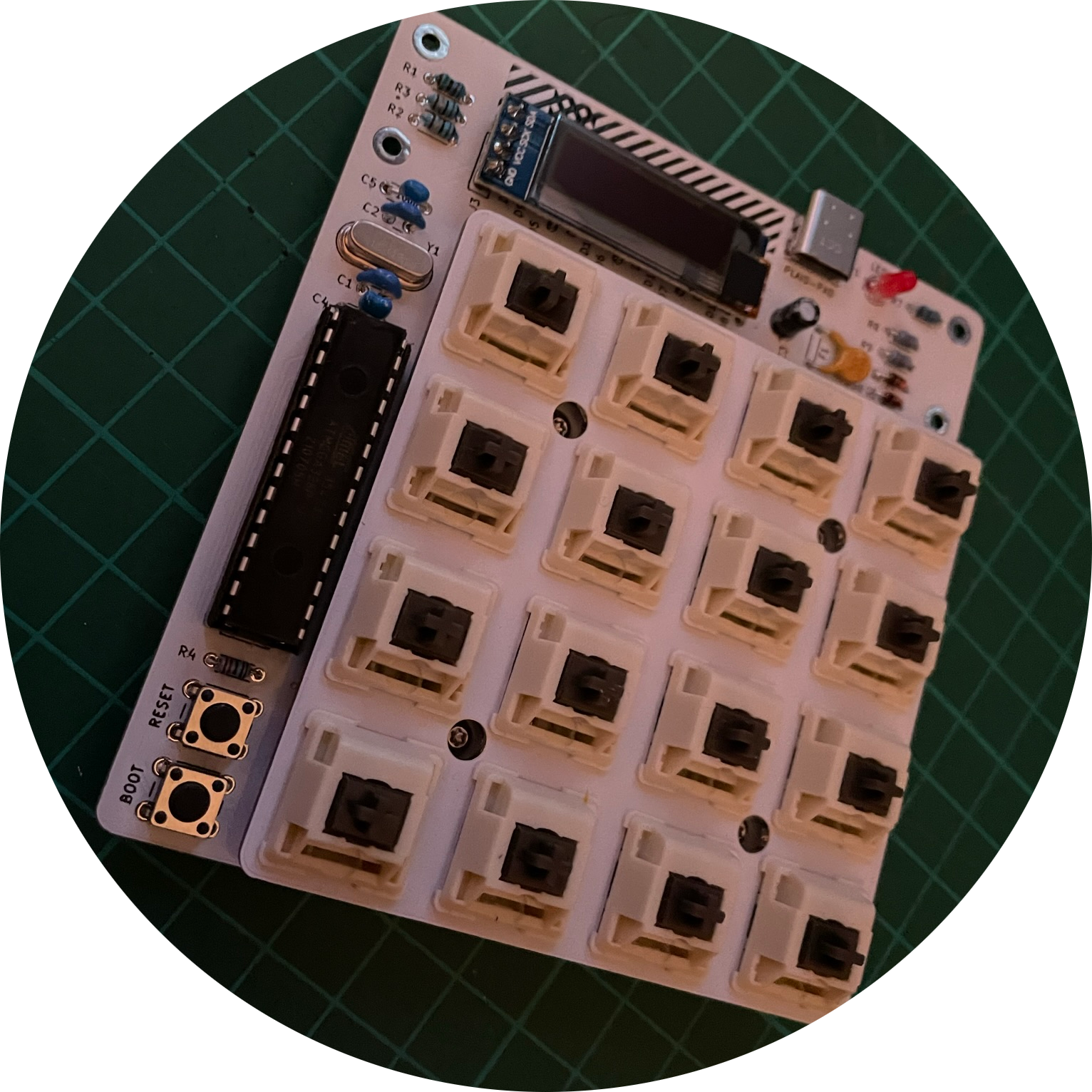
It looks like a lot of soldering work but it's done quickly and is good practice to warm up when it comes to the Plaid Keyboard.
BUILDING GUIDE
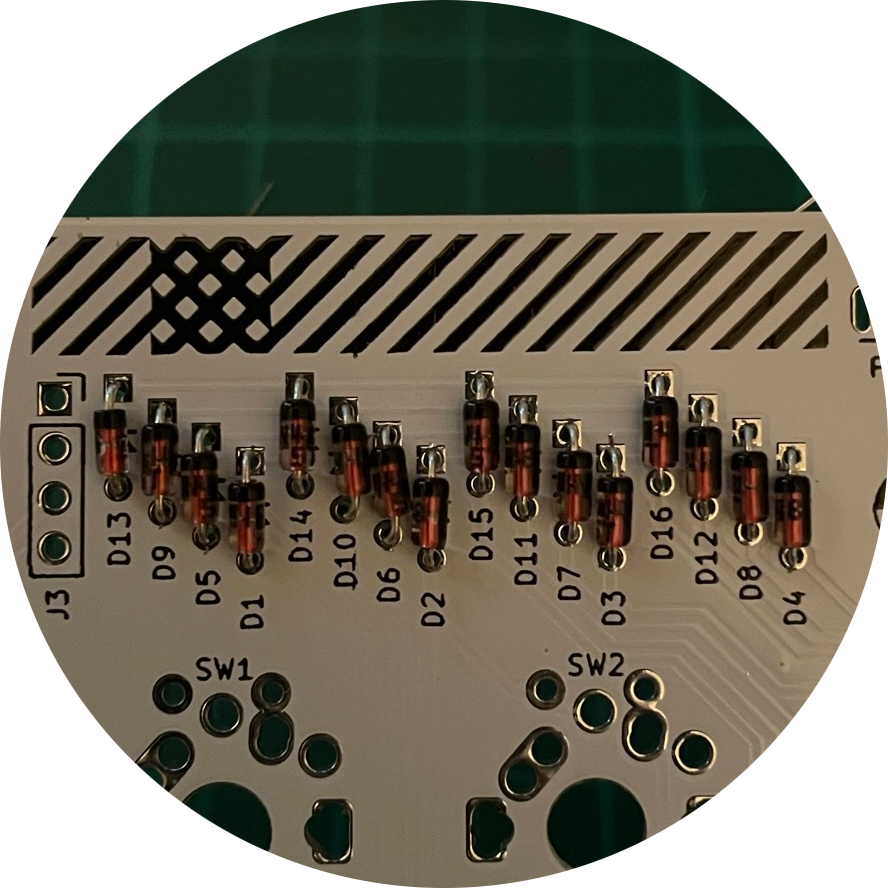
01. 1N4148 diodes
Let's start with the diodes. It's best to bend the legs while the diodes are still held together with adhesive tape. This will save you a lot of work. I bent the diodes using a plastic card (ID card etc.). It's best to bend the diodes directly behind the "diode body" so that they fit perfectly on the PCB. The diodes go in positions D1 to D16. The diodes have a specific orientation. The small black stripe on the diode marks the cathode and must go into the square hole in the PCB.
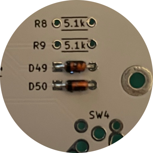
02. Zener diodes
Next come the Zener diodes. Be careful, they look very similar to the 1N4148 diodes. The Zener diodes go in positions D49 and D50. The diodes have a specific orientation. The small black stripe on the diode marks the cathode and must go into the square hole in the PCB.
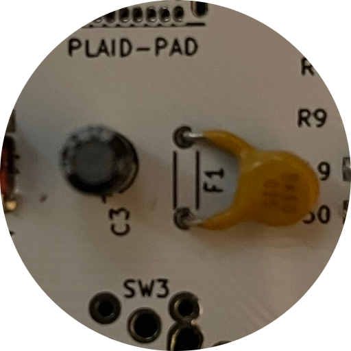
03. Resetable fuse
We solder the resetable fuse to position F1. Once it is soldered in place, bend the fuse towards the diodes so that it lies flat on the PCB.
04. Electrolytic capacitor
The electrolytic capacitor goes next to the fuse at position C3. With the capacitor, pay attention to which way you solder it. The short leg is the cathode and must go into the square hole in the PCB.
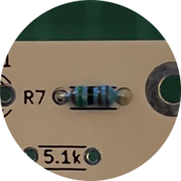
05. 1.5k Ohm resistor
Next come the 1.5k Ohm resistors at position R1 and R7. The installation direction of the resistors from left to right: brown, green, black, brown, brown.
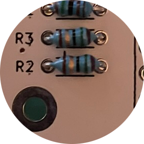
06. 75 Ohm resistor
The 75 Ohm resistors go to position R2 and R3. The installation direction of the diodes: brown, gold, black, green, purple.
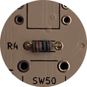
07. 10k Ohm resistor
The 10k Ohm goes on position R4. The installation direction from left to right: brown, red, black, black, brown
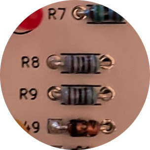
08. 5.1k Ohm resistors
The 5.1k Ohm resistors go on position R8 and R9. The installation direction from left: brown, brown, black, brown, green
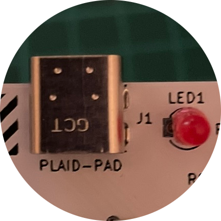
09. USB-C connector
The USB connector goes on J1. It's a bit tricky to solder because the soldering points are very small. I was able to use a hot soldering iron to spread just a little solder and then carefully heat the individual small pads and spread the solder with light strokes. It sounds more complicated than it is. If I can do it with my "soldering skills" then you can too.
10. LED
The red LED goes to position LED1. This LED signals that the pad is connected. If you don't want a permanently lit LED, you can simply leave it out. If you use it, make sure that the LED is installed the right way round. The short leg is again the cathode and goes into the square hole.
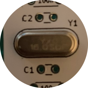
11. Crystal
The crystal goes in position Y1 and must be installed so that the print is legible.
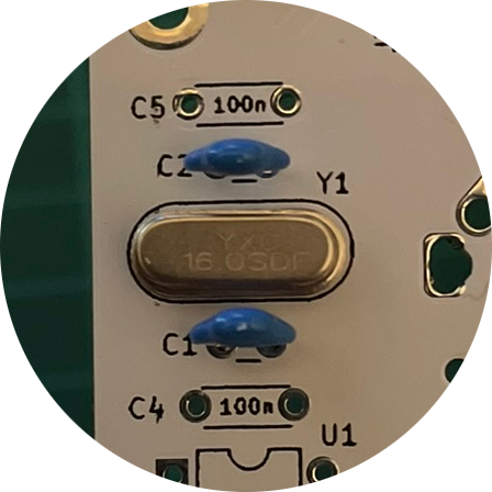
12. 22pF Capacitor
The 22pF capacitors go on C1 and C2. The 22pF ones are the ones where the legs are closer together (2.5mm).
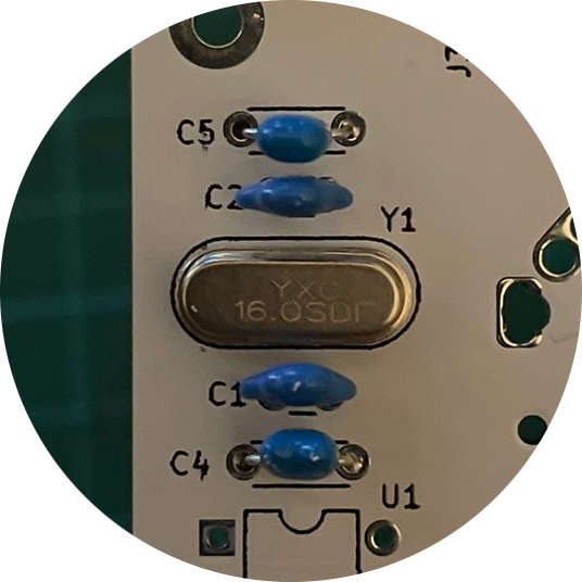
13. 0.1uF capacitor
The 0.1uF capacitors go on C4 and C5. Here the legs are a little further apart (5mm).
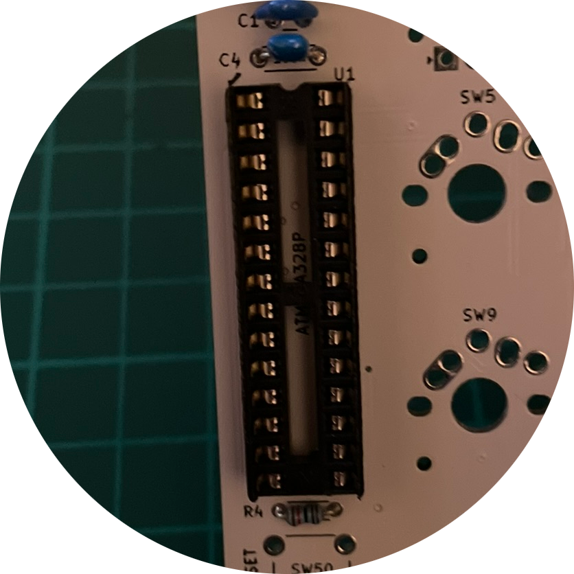
14. IC Socket
Next comes the IC socket at position U1. Here again, pay attention to the installation direction. The IC socket has a small notch that must point upwards.
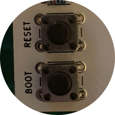
15. Tactile switches
The two switches are placed at positions SW50 and SW51. The installation direction does not matter here.
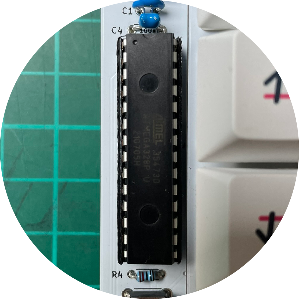
16. ATMEGA328p chip
The chip is now plugged into the IC socket. Here, too, care must be taken to ensure that the small notch is facing upwards. The small legs of the chip may need to be bent inwards so that it fits into the socket.
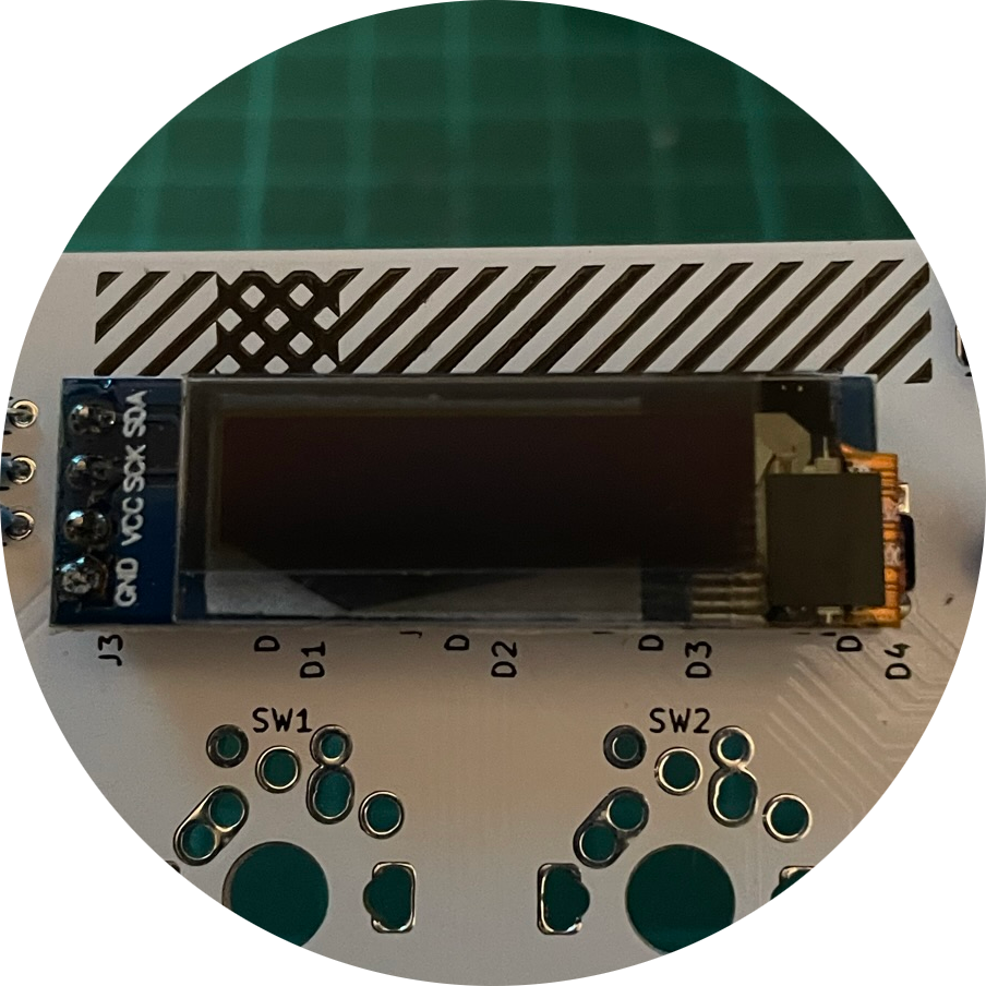
17. OLED display
If you want to operate the pad with a display, it is best to tape over the back of the display so that the diodes are not accidentally short-circuited. Once you have taped everything up, the display goes on position J3 above the diodes.

18. Testing
The soldering work is now complete. Now you can connect the pad to the computer and test it. To test, you have to bridge the contacts of the switches. I always use pointed tweezers for this. The best thing to do is to grab the QMK keyboard test website and go through switch by switch.
19. Switches
If everything works, the switches go on the Plaid Pad. To do this, simply press all the switches into the plate and place them on the PCB. Always make sure that the switches are completely flush with the PCB. The switches then need to be soldered.
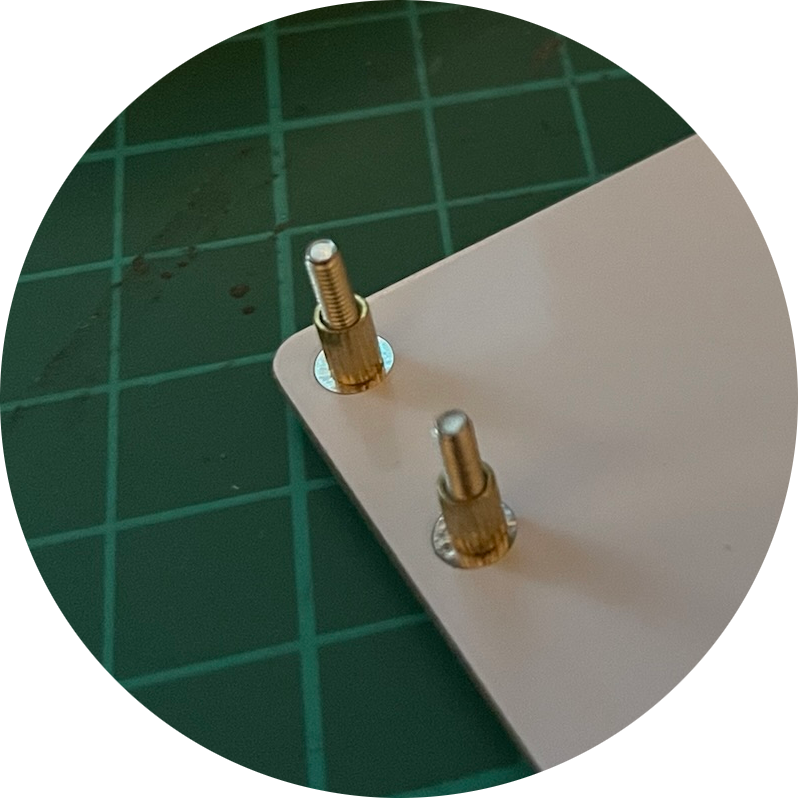
20. Spacer
If everything is soldered and working, then all you have to do is screw the spacers and the acrylic glass on the top and you've got a wonderful macro pad.
[~] BACK