Now the NC100 has rather useless hardware built in. So the idea of turning the device into a cyberdeck was a pretty obvious one. I have to say that I'm not a big vintage computer collector, I like hardware that I can use and I hope the vintage nerds will forgive me for taking the AMSTRAD NC100 apart. So what needs to happen to make the AMSTRAD NC100 more usable?
PRE
The rough roadmap of what should go into the cyberdeck and what it should be able to do:PRE
NixOS as OS
Raspberry Pi as Computer
Modern Display
Mechanical keyboard (ortholinear, Lowprofile)
Lead all ports to the outside
Those are the basic points.
The biggest effort is probably adapting the case to the requirements. In contrast to the OMNIBOOK 425, which is also lying around here, the NC100 is much easier to open and, above all, the display is easier to remove.
But before ordering lots of individual parts and starting to tinker around, a little more planning is needed.
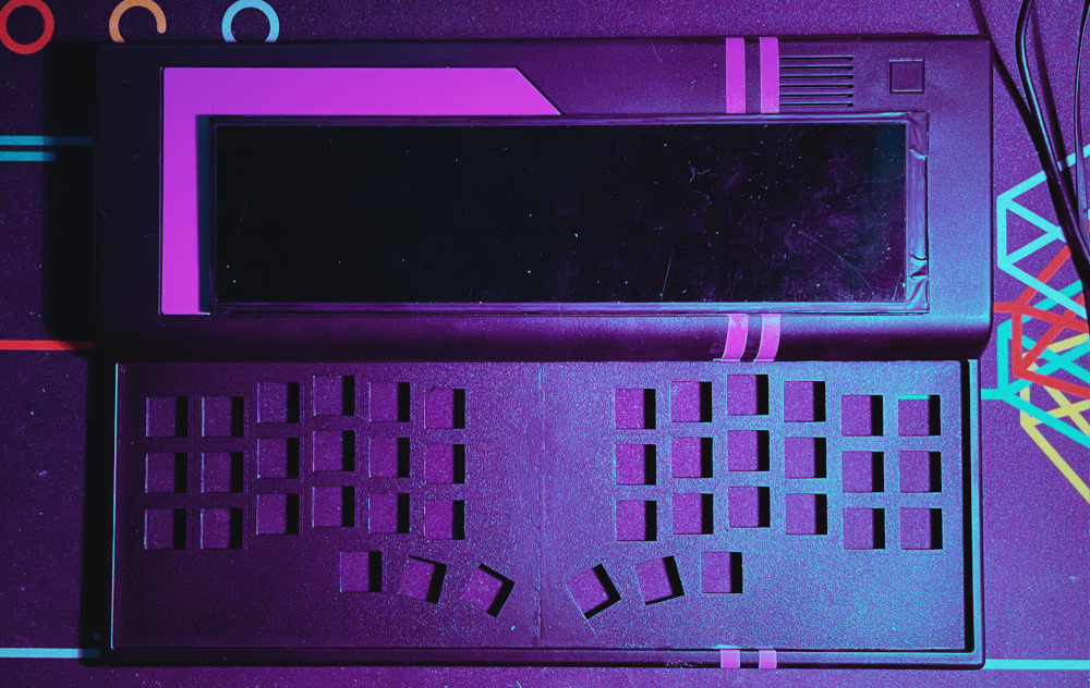
Let's start with the display. The old LCD display is nostalgically beautiful, but a little more color and resolution would be great. Inspired by the DevTerm, I searched through the various shopping platforms and came across a display that fits perfectly. It is an 8.8" display with a resolution of 1920px x 480px. So a slightly different format. The display comes with its own circuit board that is connected to the Raspberry Pi via HDMI and regulates the signal.
The all-rounder Raspberry Pi is used as the computer. The beloved NixOS with XMonad and Xmobar is installed on it. Now the Raspberry Pi lies somewhat loosely in the case of the Amstrad. So it makes sense to place the ports on the outside. The RJ54 connector is placed on the left side of the Amstrad using a built-in socket and three USB ports on the top. The keyboard is a CRKBD / CORNE. Not in the actual sense of use, however, but as a unibody split. I save myself the handwiring out of laziness and use the CRKBD PCBs instead. Kailh Choc browns go on the board as switches and first unlabeled compatible caps.
So much for the preliminary considerations. So we have a part list that looks like this:
PARTLIST
AMSTRAD NC100 Notepad

2x crkbd PCBs
42x 1N4148 Dioden
42x Kailh Choc Switches (brown)
42x Kailh Choc Keycaps
02x Pro-Micro Microcontroller
3D printed Switchplate

8.8" Display
02x USB Port
01x RJ45 Port
02x Micro USB Port

Raspberry Pi
32GB MicroSD Card
So that you can order the right parts, you have to measure, measure, measure. If you don't measure, your parts may not fit and that's frustrating. So now it's time to take care of the Amstrad and disassemble it.
DISASSEMBLING
The Amstrad is very easy to disassemble.All you have to do is loosen the 5 screws on the bottom of the device. Three of them are directly on the bottom of the case. Another is for the flap under which the beautiful Amstrad chip is located and the last screw is hidden in the battery compartment.
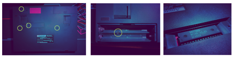
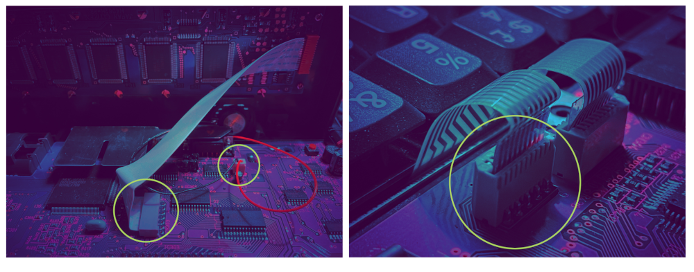
Once you have loosened all the screws and can open the Amstrad, the wonderful world of vintage computer motherboards lies before you. However, caution is still advised. The display and speaker are connected to the NC100's motherboard via a plug or ribbon cable. If you don't want to simply tear it off, lift the lid carefully; there is a lot of room to move, but be careful anyway. You can unplug or pull it out and then you can separate the two halves. You can also remove the keyboard straight away after unplugging it.
HACKEN
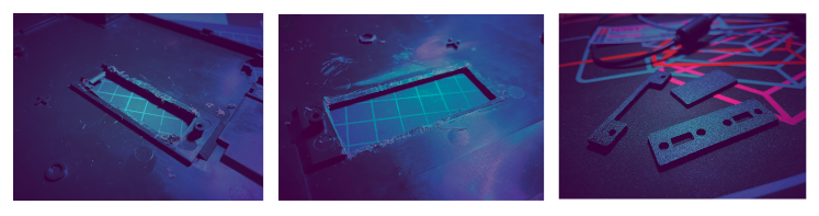
Now that the Amstrad is disassembled, all the innards can come out and we have the opportunity to measure everything that is crucial for our further planning. Let's start with what I know about: the keyboard. As mentioned above, a CRKBD/CORNE is going into the Amstrad. One of my favorite split keyboards. A quick test by placing the PCBs shows that the CORNE could fit into the case. But it would be too easy if everything went without complications. The two halves of the CORNE are normally connected using a TRRS cable. But now the two PCBs are relatively close to each other, so the option of using a TRRS cable is unfortunately out of the question. Not so bad - we'll just wire it up directly. Now the PCBs shouldn't just lie loose in the Amstrad, they should also look good. That's why there's a nice 3D printed switch plate. But for that you need the dimensions again: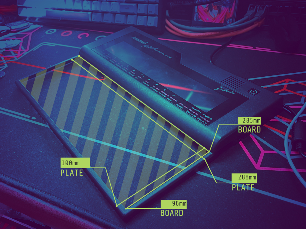
The plate can be easily placed under the frame. It is 1.5mm at the top and bottom and 2mm on the right and left. The keyboard has a space of 285mm x 96mm on the surface. The plate itself measures 288mm x 100mm. Since I'm a 00 when it comes to designing plates, PCBs or 3D-printable models, I asked around a bit. Unfortunately, there is no plate that arranges the PCBs horizontally by default. So I had to get to grips with the subject of plate design. A few Discord users were able to help me. Thanks to mini-e industry plant and M4NU for tips and assistance. But Frank also offered to help me. So I discovered the QCAD tool and it makes it very easy to design a plate to the millimeter. Now I have taken all the measurements and have an almost finished design for the plate. Almost. What is still missing is the height of the plate. To do this, the original keyboard of the Amstrad is first measured. It is 7mm high. That is not much. Luckily, I have one or two CORNEs here for comparison that I can use to measure whether everything fits.
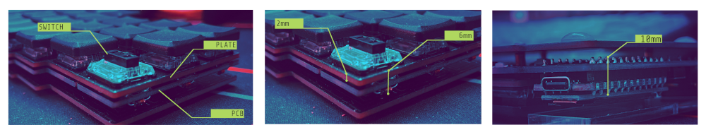
Normally the microcontrollers are placed on top of the PCB of the CORNE. But since I want a closed plate for the NB100 Cyberdeck, that's not going to work, unfortunately, because the microcontrollers are higher than the plate. The first idea was to put the microcontrollers under the PCBs. As you can see from the pictures above, the structure (without the plate) is already 10mm high. So it doesn't fit in the case. As I said - complications. But that doesn't matter. So let's look at the rest of the structure. With a standard plate of 2mm height, the structure including switches and diodes is 6mm high. That fits better into the 7mm space that is available. So the plate will be 2mm high. Since I don't have a 3D printer myself, I'll commission the good FLEAZ.
But what happens to the microcontrollers now? They are simply outsourced, i.e. the microcontrollers are soldered to the PCBs via cable and are stored, well shielded, under the display.
Next we move on to the display. The external dimensions of the display are 231mm x 65mm. So a little bigger than the original LCD display. This means that the lid of the Amstrad has to be modified. It is recommended to remove the cover that the Amstrad has on the lid. This works great with a hairdryer. Once the cover is removed, it can be measured again easily. The display fits on the small offset on which the cover sits.
Once everything has been measured so that we can order the 3D parts, we get down to business. We start with the case. There is very limited space in the case of the NB100. That's why the battery compartment and access to the Amstrad chip inside have to be removed. This is where the first vintage computer enthusiasts will scream loudly, because plastic is being removed here and it is irreparable. Once all unnecessary plastic has been removed, the flap for the Amstrad chip is glued and the cover for the battery compartment is simply put on. This makes the underside of the NB100 stylish and the inside can look a little wild.
Next comes the top of the case. Here (after checking that the installation height is correct) the keyboard switch plate is glued in. It fits perfectly where the keyboard used to be. But the plate is not the only thing. The NB100 has a wheel on the right side that was used to adjust the brightness. This is where we place our RJ45 socket. To do this, however, a piece of the case has to be removed. The best way to do this is with an old-school hacksaw. This is where we have reached the first milestone. The case is finished and ready to use. However, the old anthracite should give way to a beautiful black. So it's time to paint it. So find a place with plenty of space and unpack the paint cans. With the black, this is done relatively quickly. Let it dry. Now two pretty purple stripes should be added, i.e. tape everything up well, so that only the stripes turn purple and paint over them with purple.
When everything is thoroughly dry, the case is finally ready. Now come the innards and the keyboard.
KEYBOARD
The keyboard is a little different than if the CORNE were built as a separate stand-alone board. First, the diodes are soldered onto the PCBs. In this case, SOD-123FL SMD diodes. However, these go on the underside of the PCBs. After the diodes are soldered, the microcontrollers are soldered. The microcontroller does not go directly onto the PCBs, however, as otherwise the installation height will no longer fit and the keyboard will no longer fit in the case. So cables are connected to the PCBs and then to the appropriate pins on the microcontroller. A somewhat unusual method, but what wouldn't we do to save a few millimeters. The important thing is that the microcontrollers have to be insulated so that unwanted short circuits do not occur. It is a little more complicated, but it is necessary. Once that's done, the two halves are connected to each other. There's obviously no space for TRRS sockets either, so wire them up straight away. The penultimate step is to test the board before it's installed. Nothing is more annoying than finishing building a keyboard without having set it up first. So flash the keyboard with the wonderful QMK:The keyboard is tested with tweezers and a tool that shows me all the keystrokes. If everything works with the keyboard, it can go into the case and the switches are soldered on. The keyboard is then fully installed and ready for use.
DISPLAY
The display goes directly onto the frame that held the cover. The whole thing is fixed to the lid with a few small adhesive dots. But since the display does not fill the entire width of the recess, we cut a small section out of it, paint the whole thing purple and then glue the cover back in place. Even if it is obvious, the best way to mount the display is without it hanging on the PCB.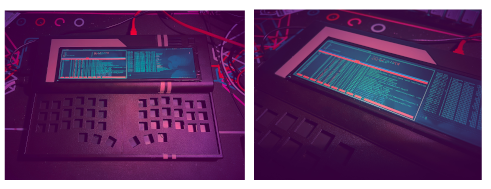
PORTS
In the next step we install the ports. These are the two power ports on the top of the case, the RJ45 on the right side and the two USB ports on the left. This is where our dealer comes in again and prints us a couple of covers so that the whole thing looks nice. The NB100 has a slot that has no use whatsoever, so it is simply closed.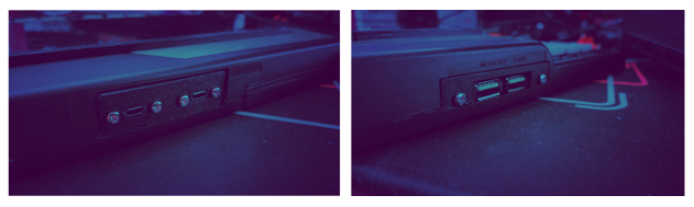
The panels are glued to the bottom of the case, but not to the top. This means we can open the case later without having to tear everything apart.
CONNECT IT!
Now that all the external components are installed, we can start with the cabling. In the first step of the cabling, USB and microUSB sockets are screwed to the panels. Storing the cables in the case is not that easy. The cables and the Raspberry Pi go into the case. The micro-USB cable for the keyboard is connected to the Raspberry Pi, the network cable and the circuit board for the display are connected to the power port. Now the top of the case can be put on top. The two microcontrollers have to be pushed between the other cables somehow. If you have succeeded in doing this, the keyboard can be connected to the Raspberry Pi. Now that most of the wiring is done, the 4 screws go back into the case and fix everything back in place. When everything is in place - the display comes. The display is glued into the recess in the top BUT! Of course, it is first connected to the board using the ribbon cable.Done - the NB100 Cyberdeck!
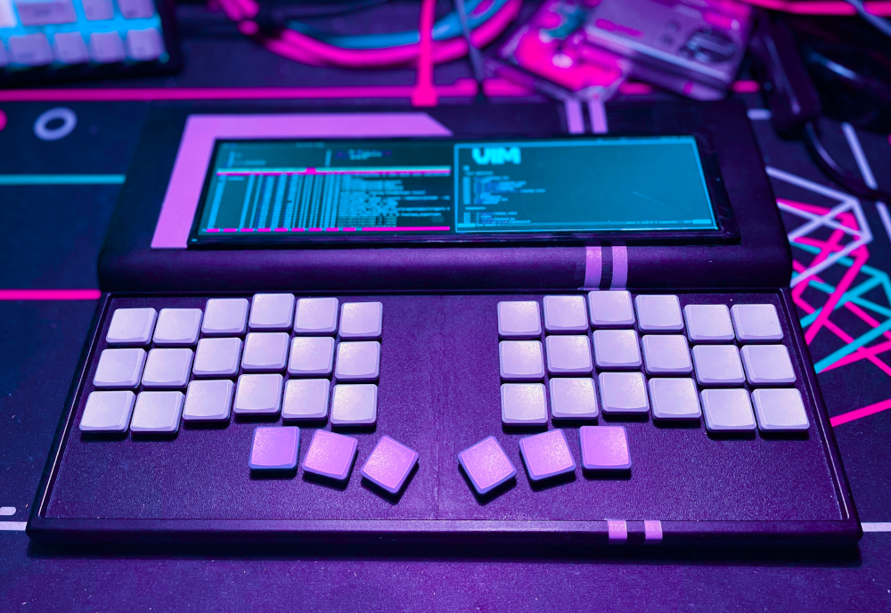
The NB100 in the vastness of the network:
[-] Post in Keyboard Builders Digest
[-] Article on Hackaday.com
[-] Hackaday.io
[-] Hackster.io
[-] MagPi Magazine
Thanks and Credits:
[-] Fleaz - 3D Print Parts
[-] Ink_0ne - SMD Dioden
[-] Revenge Day - Music
[-] Frank - Tips and Connections
[-] KBD.NEWS - Mention in Keyboard Builders Digest