In Teil 1 (LINK) ging es um die Überlegungen die es bedarf bevor es losgeht mit der Bastelei. Weiter geht's mit einem Hybrid aus Planung und Spaß am Gerät (... das wir uns erst bauen).
Part 1 (LINK) was about the considerations that are needed before you start tinkering. We continue with a hybrid of planning and having fun with the device (... which we are building first).
Microcontroller
In order for the keyboard to do what it is supposed to do - pass on the characters we type to the computer - it needs more than just switches.This is where our microcontroller comes into play. It recognizes which key is pressed and compares the code running on it to determine which character the key belongs to and sends this on to the computer.
Which microcontrollers are suitable?
ATmega32u4 is suitable as a DIY keyboard controller (DOCU), STM32F303xC (DOKU) and AT90USB1286 (DOCU).
The advantage is that the microcontroller can regulate communication between USB and keyboard without much effort. Fortunately, you don't have to create your own PCBs to use the controller. There are ready-made boards that are equipped with this controller. Here you can simply solder the contacts of the switches to the pins of the board and these are passed on to the controller accordingly.
The following boards are suitable for a DIY keyboard:
[+] Pro Micro (Datasheet)
[+] Elite C (same Board like "Pro Micro" but with USB-C Connector)
[+] Teensy 2.0 (Datasheet)
[+] QMK Proton C (Datasheet)
[+] Teensy++ 2.0 (Datasheet)
The next rabbit hole? Yes - if you want to deal with microcontrollers. If not, you take the best documented boards and those are Teensy 2.0 and Teensy++ 2.0. In that case, the ATmega32u4 is a little better documented than the AT90USB1286 - but that's just a minor detail.
I chose the Teensy 2.0 with ATmega32u4 microcontroller.
When the board + microcontroller are selected, it's all about the controller's firmware.
Here, too, fortunately, the wheel doesn't have to be reinvented. In the first part, I already linked the Keyboard-layout-editor. With this tool, you have the option of grabbing the raw data from your layout and passing it on to another practical tool.
This is also where you specify which pins are used for vertical and which for horizontal rows, but more on that later. Here is the link: Keyboard-Firmware-Creator
The tool gives you all the rotary controls you want. You can define the entire keyboard layout, create different layers (particularly useful for 65% and smaller keyboards), you can put your LEDs directly into the firmware and so on.
If you are happy with your settings, the whole thing is compiled, the tool spits out a *.hex file and flashes it onto the microcontroller. That takes care of the microcontroller + software.
What is also left out of the keyboard firmware builder is the wiring of the switches.
Wiring
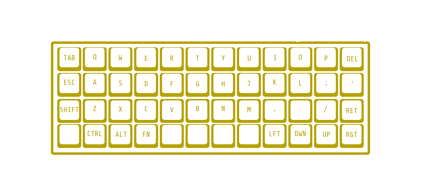
The basic concept of wiring is a grid of rows and columns. This is easiest to understand with the Plankh Ortholinear Keyboard.You don't need much for the basic wiring - what you need is:
[+] Wire [+] Solder [+] x-Diodes (x = Number of Switches / 1N4148 Diodes)
The diodes are needed in case the correct key signal still reaches the microcontroller, even if several keys are pressed at the same time. This is particularly useful for key combinations.
Once the plate is fitted with the switches, it's time to solder. Standard switches have 2 pins. One is used for the horizontal connection and the diodes, the other for the vertical connection. The only important thing is that the same pins are always used.
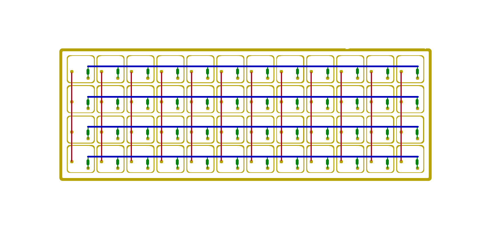
red - vertical wiring green - diodes blue - horizontal wiring
This connects the switches to each other. The connection to the board with the controller is still missing.
As before, the rows and columns are now connected to the board. To do this, you need exactly one contact from each column to the board and one from each row. These are then placed on the board as specified in the firmware.
In theory, we now have a functional, homemade keyboard! Connect the cable - open VIM and get started.
When designing the case, there are of course no limits to your imagination. My case is made from an old piece of board from which the inside was sawn out, the plate for the keys and the underside are the side wall of an old speaker - sand everything down well - done.
[~] BACK